
The NoblePro® E10i treadmill offers an impressive selection of features designed to make your workouts at home more effective and enjoyable.
Base Model No
NPE78850 E10bnf
Screen Model No
NPE78851 E10is
NoblePro Ltd assumes no responsibility for personal injury or property damage sustained by or using this product.

NoblePro Ltd assumes no responsibility for personal injury or property damage sustained by or using this product.

Always unplug the power cord immediately after use, before cleaning the treadmill and before performing the maintenance and adjustment procedures described in this manual.
Never remove the motor cover unless instructed to do so by an authorised NoblePro Ltd representative.
Additional servicing, other than the procedures in this manual, should be performed by an authorised service representative only.


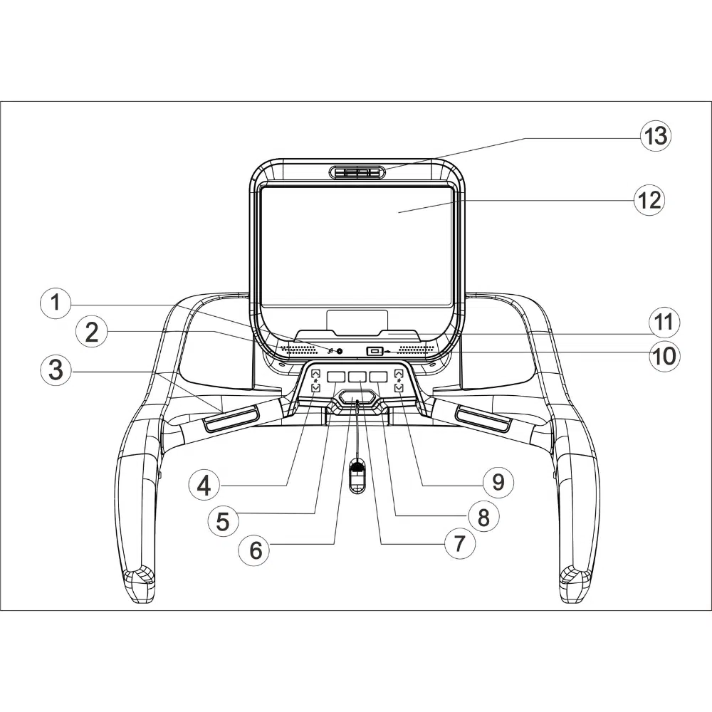
(1) Fan
(2) Touch Screen
(3) Bottle holder
(4) Handrails
(5) Pulse Sensor
(6) Running belt
(7) Foot rail
(8) Belt adjustment screws
(9) Cushion system
(10) Safety key
(11) Control pad
(12) Tray
| Maximum User Weight | 180kg / 397lbs |
|---|---|
| Dimensions ( L x W x H) | 2048 x 955 x 1545mm |
| Running Area | 1555 x 580 mm / 61 x 23" |
| Incline Levels | 0 - 16% |
| Machine Weight | 155 N.W kg (341lbs) / 172 G.W. kg (380 lbs) |
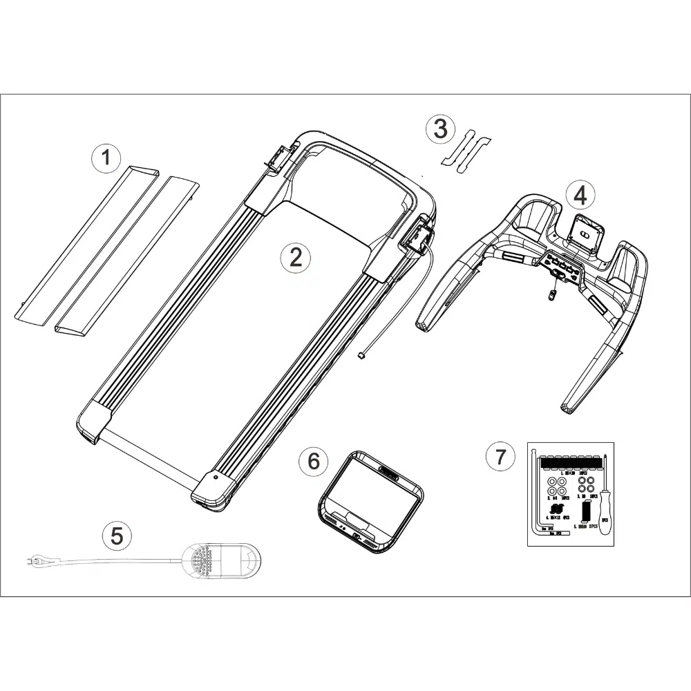
(1) Base frame
(2) Upright cover x 2
(3) Console Frame
(4) Screen
(5) Left and Right upright posts
(6) Safety key
(7) Assembly Kit

| Description | Quantity |
|---|---|
| 1. M8*20 Screws | 16 |
| 2. Ø8 Washers | 18 |
| 3. R8 Washers | 18 |
| 4. M5*12 Screws | 4 |
| 5. M8*40 Screws | 2 |
| 5mm Allen Key | 1 |
| 8mm Allen Key | 1 |
| Star Screwdriver | 1 |
1. Register your product.
2. If you are unable to register online, please submit a technical ticket with NoblePro technical support for assistance
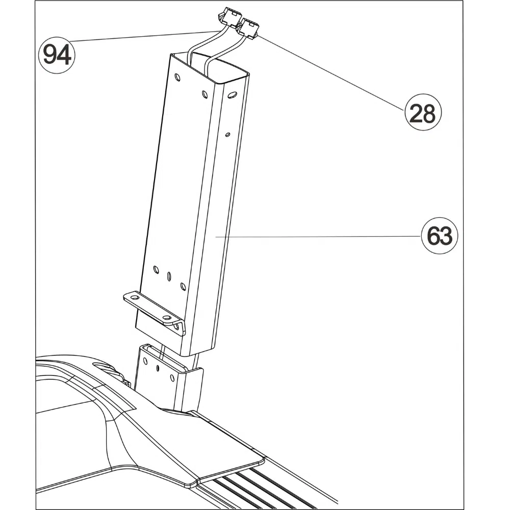
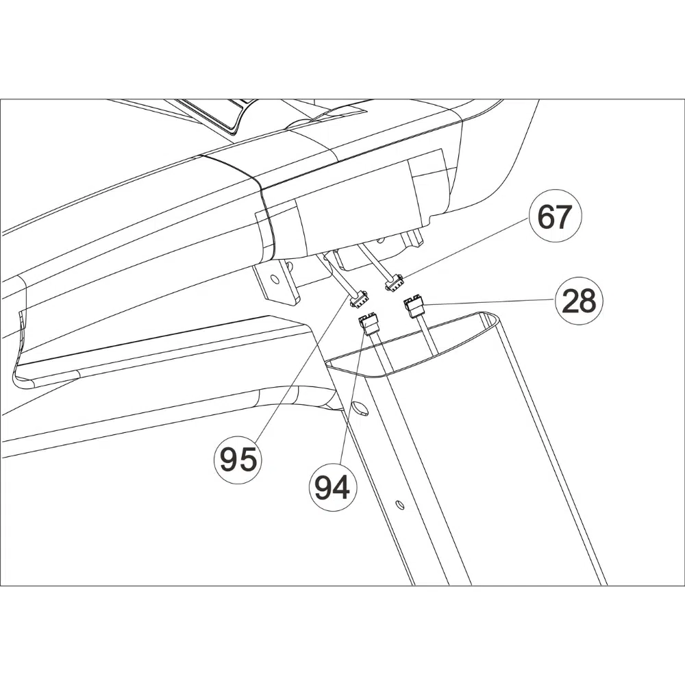
3. Identify the communication cable (28) located in the base frame. Next, identify the right upright post (63). Have a second person hold the right upright post close to the base frame. Then, feed the communication cable through the right upright post. Place the right upright post into the base frame. Make sure not to pinch any cables.
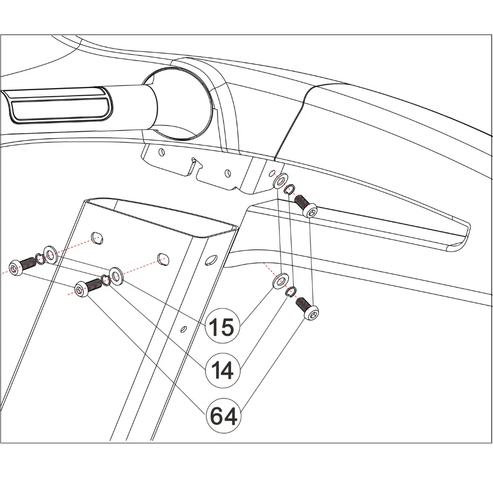
4. Place the right upright post (63) into the base frame (1). Then loosely fasten the post using 4 x M8*20(64) and 1 x M8*40 (65) screws with a flat washer (14) and spring washer (15) to the base frame.
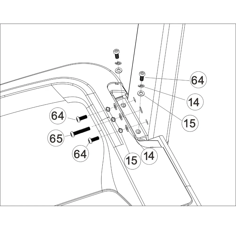
5. Place the left upright post (62) into the base frame (1). Then loosely fasten the post using 4 x M8*20(64) and 1 x M8*40 (65) screws with a flat washer (14) and spring washer (15) to the base frame.
6. Locate the communication wire (67) at the back of the Console on the right side of the console frame. Connect the communication wire (67) to the communication wire (28). Place the console frame over the uprights. Note: Be careful not to crush the wire; it should be clear of edges.
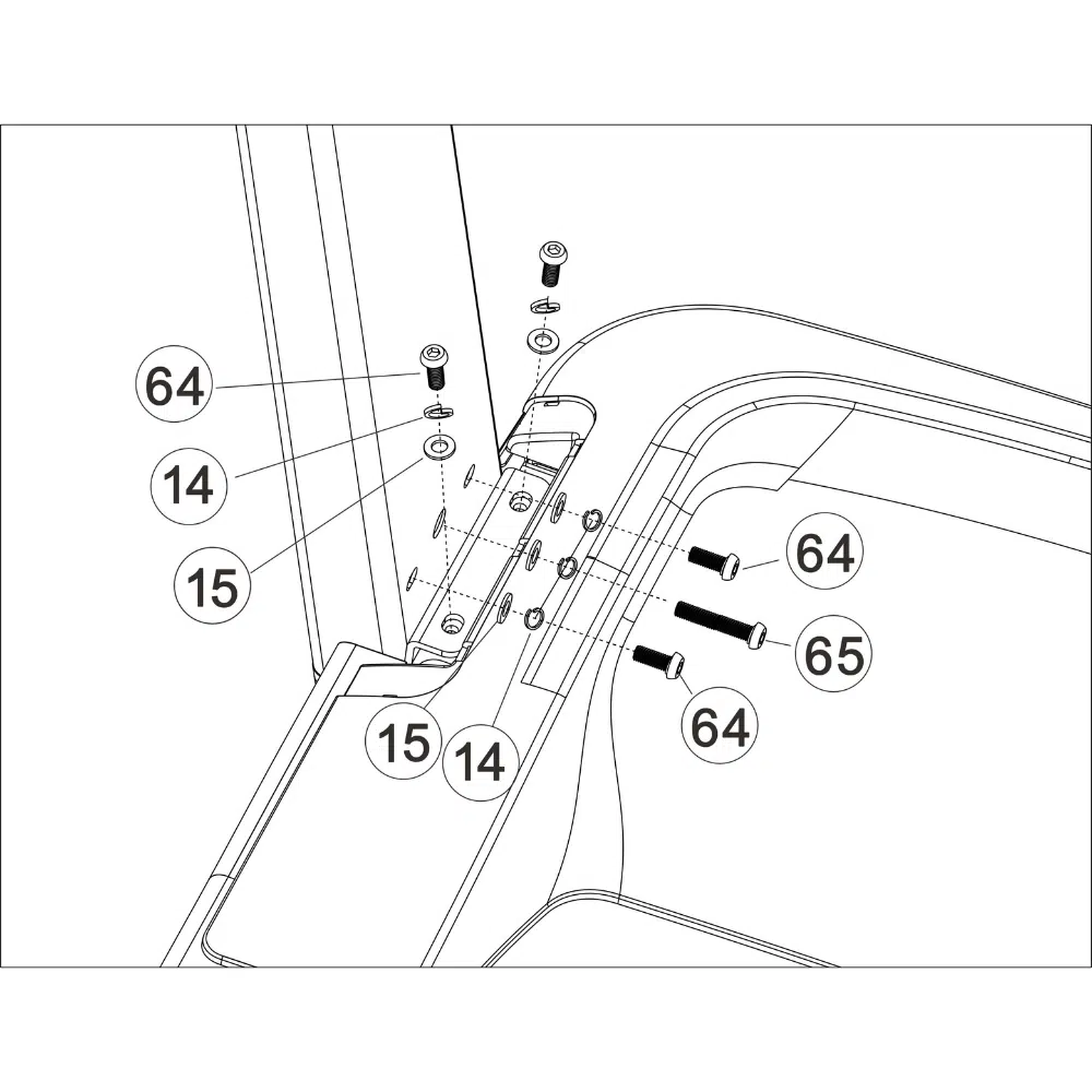
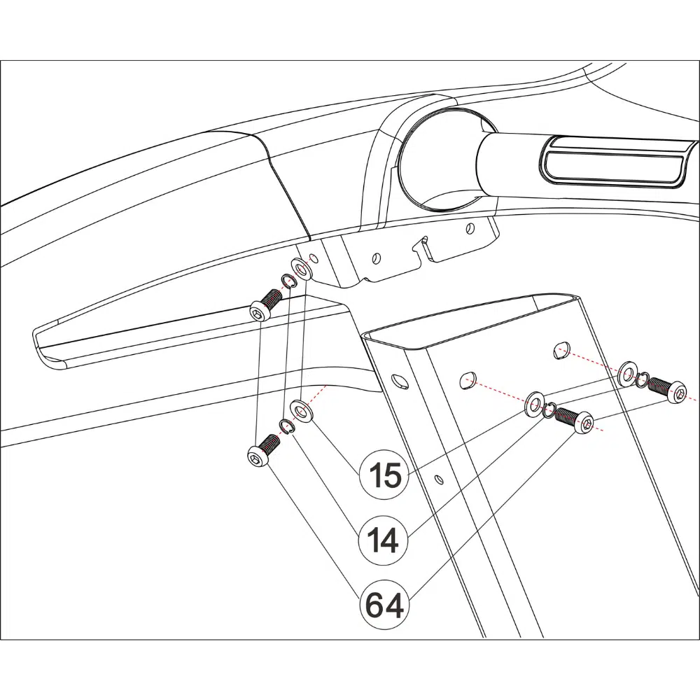
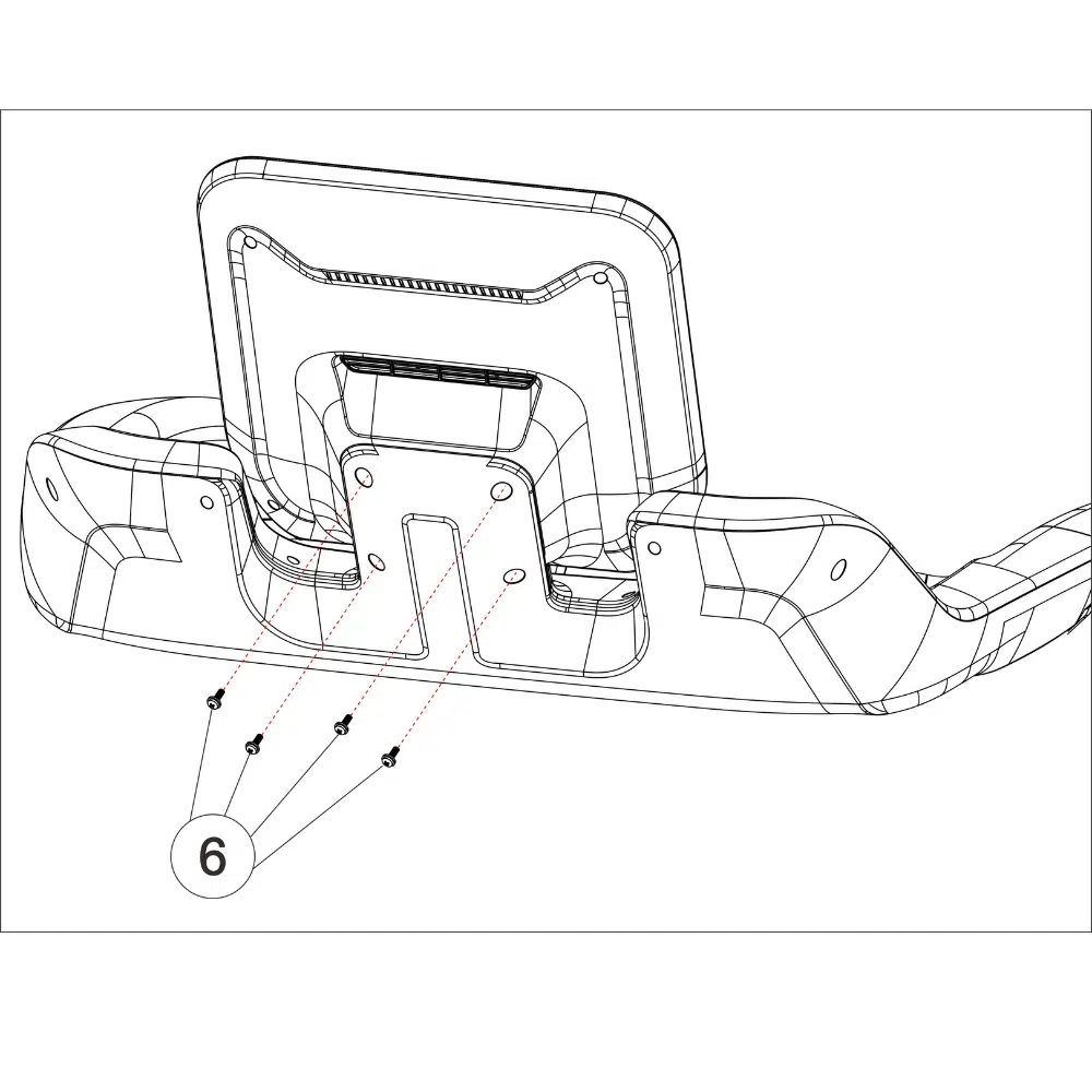
7. Use 4 x M8*20 (64) screws with a flat washer (14) and spring washer (15) to fasten the right uprights to the Console. Lightly fasten all screws until all screws have been aligned.
8. Use 4 x M8*20 (64) screws with a flat washer (14) and spring washer (15) to fasten the left uprights to the Console. Lightly fasten all screws until all screws have been aligned. Tighten all screws in step 4 and 8.
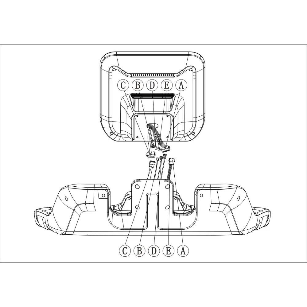
9. Place the console screen assembly on the console base. Connect the console connections: A to A, B to B C to C D to D E to E Note: The connector will make a “click” sound when secured. Gently pull them to check they do not separate.
10.Place the wires inside the base frame smoothly. Use 4 x M5*12 (6) screws to fasten the console screen assembly to the console base.
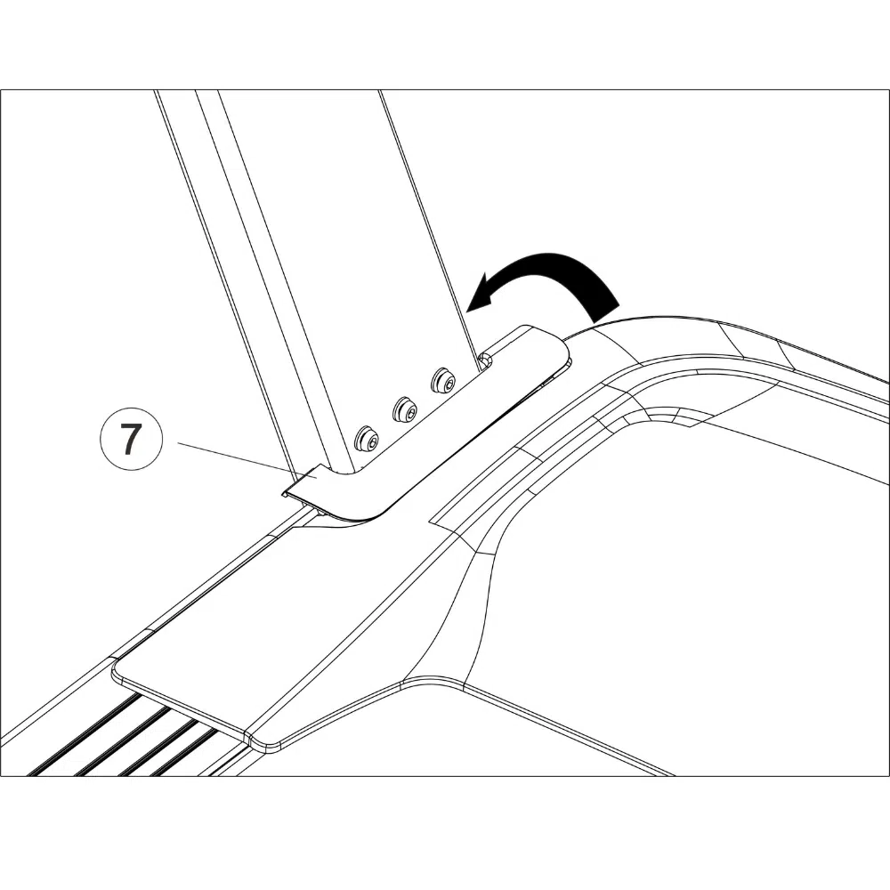
11.Place the motor insert cover on both the left (7) and right (8) upright post bases.
12. It is imperative to ensure that all parts are tightened before using the treadmill. It is advisable to place a protective mat under the treadmill and not onto a slippery, uneven surface. The tools provided can also be used for treadmill maintenance.
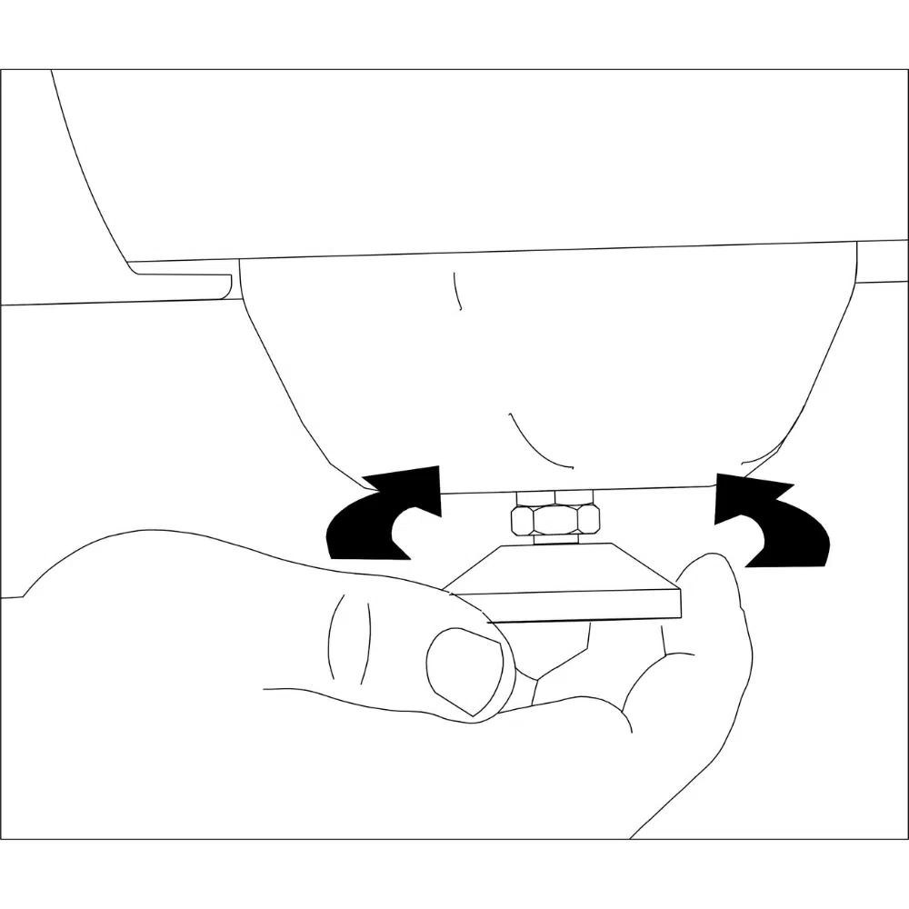
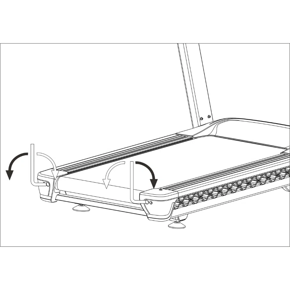
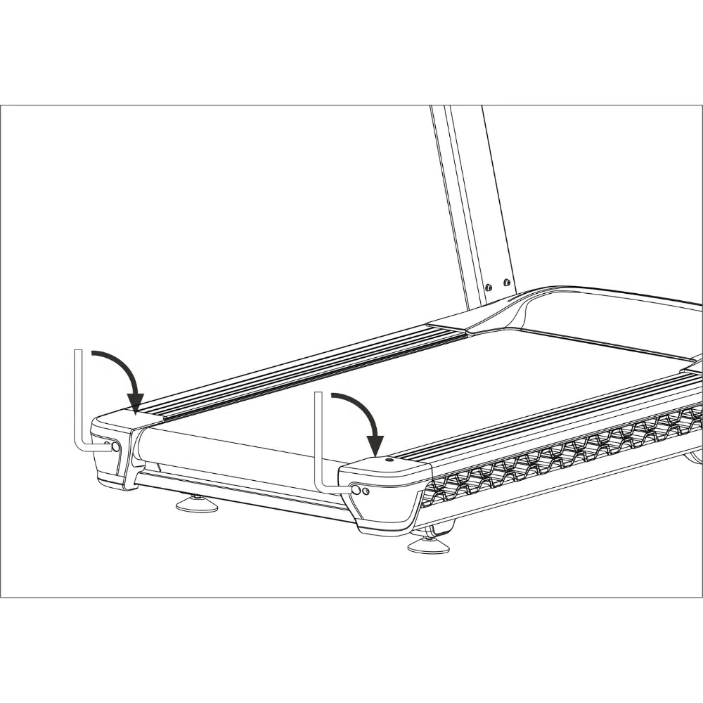
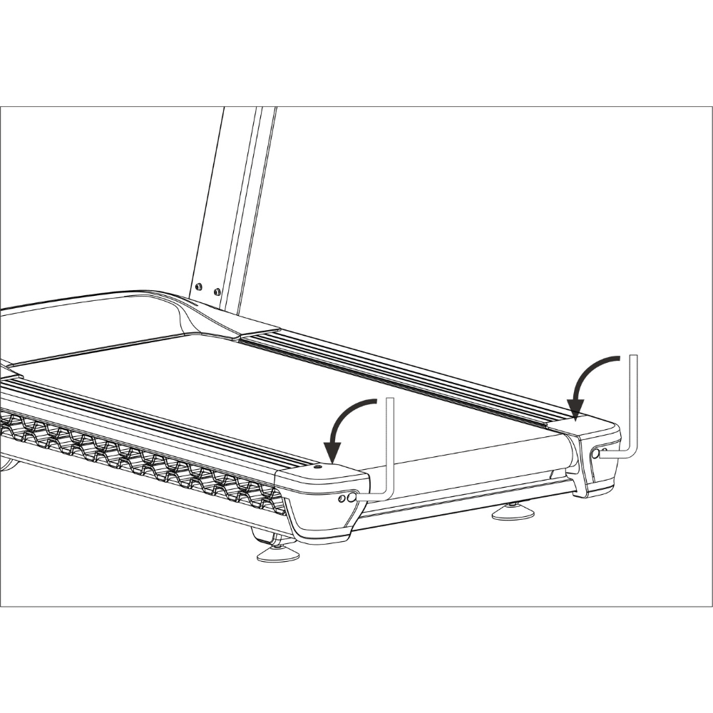
1. Level the treadmill by adjusting the feet on the back of the treadmill.
2. Once adjusted, lock the nut to secure the feet into place
1. Ensure the treadmill on level ground.
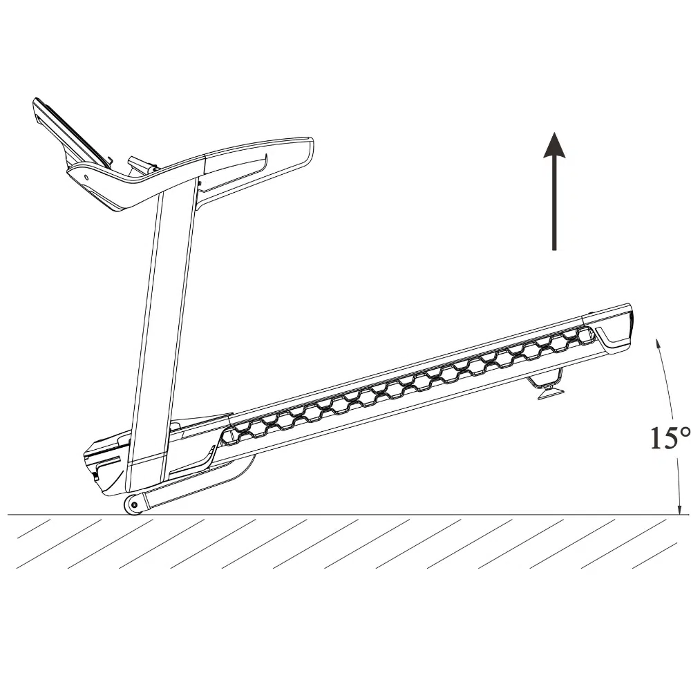
2. When handling, lift the end of the treadmill and then use the treadmill roller at the front to slowly move the treadmill.
3. Once in a suitable position, slowly lower the rear of the treadmill until it is resting on the ground.
The treadmill can be damaged by sudden voltage changes in your home’s power. Voltage surges, spikes, and noise interference can result from weather conditions or other appliances being turned on or off. To decrease the risk of damaging the treadmill, use a surge suppressor that complies with or exceeds UL 1449 or BS 1363 requirements. The surge suppressor must be electrically rated for 240 volts AC and a minimum of 13 amps.
Failure to use a properly functioning surge suppressor could result in damage to the control system of the treadmill and serious injury to users.
The treadmill must be grounded. If it should malfunction or break down, grounding provides a path of least resistance for an electric current to reduce the risk of electric shock.
Plug the power cord (A) into a surge suppressor and plug the surge suppressor into an appropriate outlet that is properly installed and grounded in accordance with all local rules and regulations.
The outlet must be on a nominal 240-volt circuit capable of carrying 16 or more amps.
To avoid overloading the circuit, do not plug other electrical devices, except for low power devices such as cell phone chargers, into the surge suppressor or an outlet on the same circuit.
If you do not do this, you may damage the console displays or other electrical components.
Plugin the power cord (A) into the socket and into the treadmill power inlet (B).
Next, locate the power switch on the treadmill frame near the power cord.
Press the power switch into the “on” position.
Alternatively, you can also reboot / shutdown the treadmill from the screen.


The safety key (1) is designed to bring the treadmill to a stop if disconnected. Insert the key into the Console as indicated, and securely attach the clip (2) to your clothing.
IMPORTANT: The treadmill will not function without the safety key being placed in the Console.
The NoblePro E10i also has additional safety key settings you can enable if required.

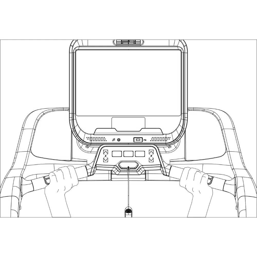
(1) Aux cable plug in
(2) Speakers
(3) Heart rate sensors
(4) Incline adjustment key
(5) Stop button
(6) Safety key
(7) Cool down
(8) Start button
(9) Speed adjustment key
(10) USB plug
(11) Tablet holder
(12) 15.6 inch LCD touch screen
(13) Fan
The treadmill needs to be connected to WiFi to ensure your software is up to date. To connect the treadmill to WiFi, follow the guide here.

Once the treadmill is connected to the internet, open the System Updates app. This system will check for any operating system updates and provide an option to update, if a later version is available. The user interface can be updated with the guide here.

It is important to keep your apps up to date using the Aurora Store, to ensure you get the most out of your treadmill. You will need to set up the Aurora Store on first use. You can download and update all apps through this Store.

An on-screen app that is running in the background of another app / screen interface. Thus meaning, none of it’s activities or services are visible to the user in the foreground. The background apps can be enabled by following this guide here.

The E10i can connect to multiple devices that your wish to enhance your workouts. The guides below will help you to do this:
The E10i has been made to be fully customisable when it comes to how you run, walk and train. Our development team have added some additional settings to personalise your experience.
The treadmill has built in handgrip heart rate monitors so please ensure to remove the protective plastic from the handgrips before use. For the most accurate heart rate reading, hold onto the handrails and avoid movement for 15 seconds or more.
Please regularly clean the treadmill and keep the running belt clean and dry.
1. First, press the power switch into the “OFF” position and unplug the power cord.
2. Wipe exterior parts of the treadmill with a damp cloth and a small amount of mild soap.
IMPORTANT: Do not spray liquids directly onto the treadmill.
3. To avoid damage to the Console, keep liquids away from the Console.
4. Then, thoroughly dry the treadmill with a soft towel.
The maintenance manager offers information on when your next maintenance checks are needed.

Belt lubricating should be undertaken every 300 km or 3 months, whichever comes first. The running belt is lubricated with a high-performance silicone lubricant to reduce the friction between the running belt and the running board. If the lubrication is inadequate, the belt will not operate smoothly.
1. Before checking the lubrication on your treadmill belt, remove the safety key and UNPLUG THE POWER CORD.
2. Run your finger along the underside of the belt. If there is no lubricant residue on your finger’s lubrication is needed.
3. To add lubrication to the running belt, remove the lubrication cover (36) and add 15ml of silicon lubricant.
4. Turn the treadmill on using easy start mode and let it run for 10 mins at 12 km/h.
5. Repeat the process until there is an even film of lubricant on the running belt.

If the running belt is off centre, remove the safety key and UNPLUG THE POWER CORD.
If the running belt has shifted to the left (viewed from the back), use the 6mm hex key to turn the left idler roller screw clockwise ½ a turn; if the running belt has shifted to the right (viewed from the back), turn the right idler roller screw clockwise ½ a turn.
Then, plug in the power cord, insert the safety key and run the treadmill for a few minutes. Repeat until the running belt is centred.
If the running belt slips when walked on, first remove the key and UNPLUG THE POWER CORD.
Using the 6 mm hex key, turn both idler roller screws a ¼ of a turn clockwise at a time until you can lift each edge of the running belt 3 to 4 inches (8 to 10 cm) off the running board.
Be careful to keep the running belt centred. Then, plug in the power cord, insert the safety key, and carefully walk on the treadmill for a few minutes. Repeat until the running belt is sufficiently tightened.
1. To loosen the running belt, first, remove the key and UNPLUG THE POWER CORD.
2. Then using the hex key, turn both idler roller screws a ¼ a turn counter clockwise at a time until you can lift each edge of the running belt 3 to 4 inches (8 to 10 cm) off the walking board. Be careful to keep the running belt centred.
3. Then, plug in the power cord, insert the safety key and run the treadmill for a few minutes.
4. Repeat until the running belt is properly tightened.


| Issue | Possible Causes | Solution |
|---|---|---|
| The treadmill does not turn on | A No power | Plugin the power cable |
| B Safety key not detected | Insert safety key | |
| C Faulty communication circuit | Check control panel and communication cables | |
| D Treadmill power switch in "OFF" position | Turn the power switch to the "ON" position | |
| E Blown fuse | Replace the fuse | |
| The console screen does not display anything | The power cord is not connected | Connect the power cord and check the socket |
| B The power switch is on the "OFF" position | Turn the power switch to the "ON" position | |
| C Power overload or damaged driver | Push the overload protection button. Replace the driver | |
| D Communication cable faulty | Replace the communication cable | |
| E Digital watch is damaged | Replace the digital watch | |
| F (LCD) backlight is not bright | Adjust, replace or repair the backlight | |
| The treadmill display is missing characters | A An issue with the display connections | Repair or replace display they |
| B The display is not fixed in position and sliding around | Repair or replace the splay | |
| C Faulty display driver IC | Repair or replace display driver IC | |
| Treadmill running belt not moving smoothly | An Excessive resistance on the transmission system | Adjust the transmission parts and / or lubricate accordingly |
| B Running belt is too tight | Loosen running belt | |
| C Running belt is too loose | Tighten running belt | |
| D Torque requirements too small or too high | Adjust the torque potentiometer accordingly | |
| E Lack of running belt lubrication | Lubricate the running belt as directed in the user manual | |
| F Motor belt is slipping | Tighten the motor belt | |
| G Over lubrication | Remove excessive lubrication on running belt and drive belt | |
| Static shock | Static electricity is not being earthed | Ensure the plug earth quality is good |
| B High static cloths used during exercise | Use natural material clothing during exercise | |
| Buzzing noise | A Plug power is out of phase | Inspect the plug outlet phase quality |
| B Incorrect voltage supply | Ensure the correct voltage is supplied to the treadmill | |
| Safety key | A Missing safety key | Place the safety key in the designated area |
| B Faulty magnetic sensor | The safety key magnetic sensor is stuck. Repair or replace magnetic sensor. | |
| Communication failure | A Communication cable faulty | Reconnect the communication cables |
| B Damaged communication cable | Replace communication cable | |
| C Communication cable connection faulty | Replace effected cables | |
| D IC drive cable faulty | Replace the IC drive cable | |
| Motor stalls | A Loose motor connection cables | Check wire connections are tight or replace the motor |
| B Motor controller board faulty | Replace the IC drive | |
| C External ac voltage is too low | Undertake electrical supply troubleshooting where the treadmill is plugged in | |
| Over-current protection | A Treadmill overloaded | Rotate the motor by hand and safely try again |
| B Excessive friction in driver motors | Inspect and maintain transmission components | |
| C Motors damaged | Replace motor | |
| D Motor controller damaged | Replace IC drive | |
| Motor error | A Motor cable connection faulty | plug machine line again |
| B Motor is shorting internally | change the motor | |
| C Motor is idling | The motor current is too low. Replace the motor |


| No. | Part Code | Description |
|---|---|---|
| 1 | E10-BS-COM-FRAME | Frame - main |
| 2 | E10-BS-COM-DUST-SHIELD | Electronics dust shield |
| 3 | GN-GN-F-ST4.8X16 | Screw ST4.8X16 (self tap) |
| 4 | GN-GN-FSH-M4x10 | Hex socket head M4x10 |
| 5 | E10-BS-PL-MOTORCOVER-TOP | Motor cover - Top |
| 6 | GN-GN-FSH-M5X12 | Hex socket head M5X12 |
| 7 | E10-BS-PL-MOTOR-COVER-IN-L | Motor cover insert - Left |
| 8 | E10-BS-PL-MOTOR-COVER-IN-R | Motor cover insert - Right |
| 9 | E10-BS-PL-MOTORCOVER-FR | Motor cover - Front |
| 10 | E10-BS-PL-MOTORCOVER-INS | Motor cover insert part |
| 11 | E10-BS-F-MOTORCOVER-MOUNT | Motor cover mounting plate |
| 12 | E10-BS-M-BRACKET | Motor bracket |
| 13 | GN-GN-FSH-M8x16 | Hex socket head M8x16 |
| 14 | GN-GN-WS-8x2.1 | Spring washer Φ8x2.1 |
| 15 | GN-GN-W-8x1.6 | Washer Φ8x1.6 |
| 16 | E10-BS-M-DC3CHP5400 | 3 Continuous Horsepower (CHP) motor (DC) 5400 rpm |
| 17 | GN-GN-FSH-M8x12 | Hex socket head M8x12 |
| 18 | GN-GN-W-10x2 | Washer Φ10X2 |
| 19 | GN-GN-F-LCKNUTM10 | Hex lock nut M10 |
| 20 | GN-GN-FSH-M8X55 | Hex socket head M8X55 |
| 21 | E10-BS-EL-POWERINLET-C14 | Power inlet (C14) 220v |
| 22 | GN-GN-F-ST2.9X8 | Screw ST2.9X8 (self tap) |
| 23 | GN-GN-EL-POWER_TYPE_G | Power inlet cable with 13A Type G plug |
| 24 | E10-BS-EL-POWER-SWITCH | Power on/off switch |
| 25 | GN-GN-FSH-M4x10 | Hex socket head M4x10 |
| 26 | E10/E8.2-BS-EL-MCB | Motor Control Board (MCB) 220v |
| 27 | E10-BS-EL-POWER-12V | Power supply (12v) |
| 28 | E10-BS-CB-COMM-BASE | Cable (base) (communication) (NPE78850) |
| 29 | E10-BS-M-INCLINE | Incline motor (0-16%) |
| 30 | GN-GN-FSH-M10x45 | Hex socket head M10x45 |
| 31 | GN-GN-FSH-M10X70 | Hex socket head M10X70 |
| 32 | E10-BS-COM-RUNBELT | Running Belt (3165x560x2) |
| 33 | E10-BS-COM-RUNBOARD | Running Board |
| 34 | E10-BS-COM-LUB-TUBE | Lubrication tube |
| 35 | GN-GN-F-ST4.2x13 | Screw ST4.2x13 (self tap) |
| 36 | E10-BS-COM-LUB-CAP | Lubrication cap |
| 37 | E10-BS-PL-CUSHION-INSERT | Cushion anti-shock insert |
| 38 | E10-BS-PL-CUSHION-BOARD | Running board cushion anti-shock |
| 39 | GN-GN-FBH-M8x45 | Hex socket button head M8x45 |
| 40 | GN-GN-F-LCKNUTM8 | Hex lock nut M8 |
| 41 | E10-BS-ASS-ROLLER-FRONT | Front roller assembly |
| 42 | GN-GN-FSH-M10x35 | Hex socket head M10x35 |
| 43 | E10-BS-M-BELT | Transmission Belt |
| 44 | E10-BS-ASS-ROLLER-REAR | Rear roller assembly |
| 45 | GN-GN-FSH-M10X85 | Hex socket head M10X85 |
| 46 | E10-BS-PL-RAIL | Foot rail |
| 47 | E10-BS-PL-RAIL-FIX | Foot rail fixture |
| 48 | GN-GN-F-ST4.2X16 | Screw ST4.2X16 (self tap) |
| 49 | E10-BS-PL-POST-COVER-L | Post / upright cover - Left |
| 50 | E10-BS-PL-POST-COVER-R | Post / upright cover - Right |
| 51 | E10-BS-PL-ROLLER-COVER-L | Rear roller cover - Left |
| 52 | E10-BS-PL-ROLLER-COVER-R | Rear roller cover - Right |
| 53 | E10-BS-COM-LEVEL-BASE | Leveling base |
| 54 | E10-BS-COM-LEVEL | Leveling foot |
| 55 | GN-BS-PL-PAD3 | Absorption pad |
| 56 | E10-BS-COM-FRAME-INCLINE | Frame - incline |
| 57 | E10-BS-F-INCLINE | Frame incline shaft |
| 58 | GN-GN-FSH-M10x40 | Hex socket head M10x40 |
| 59 | E10-BS-COM-WHEEL-FRONT | Front wheel |
| 60 | E10-BS-COM-WHEEL-FRONT-BR | Front wheel - bearing |
| 61 | GN-GN-FSH-M10x60 | Hex socket head M10x60 |
| 62 | E10-BS-FR-POST-L | Post / upright - Left |
| 63 | E10-BS-FR-POST-R | Post / upright - right |
| 64 | GN-GN-FSH-M8x20 | Hex socket head M8x20 |
| 65 | GN-GN-FSH-M8x40 | Hex socket head M8x40 |
| 66 | E10-BS-FR-FRAME-CONSOLE | Frame - console |
| 67 | E10-BS-CB-COMM | Cable (post / upright) (communication) (NPE78850) |
| 68 | E10-BS-FR-CONSOLE-BUTTONS | Frame - console buttons |
| 69 | GN-GN-FSH-M8x16 | Hex socket head M8x16 |
| 70 | E10-SC-PL-SCREEN-FRONT | Screen cover - front |
| 71 | GN-SC-COM-SPEAKER | Speaker (8ohm 5w) |
| 72 | E10-SC-COM-TABLET | Screen tablet bracket |
| 73T | E10-SC-ASS-NPE78851PAR | E10i screen internals (NPE78851) |
| 73C | E10-SC-ASS-NPE78852PAR | E10s screen internals (NPE78852) |
| 74 | E10-SC-EL-PCB-AUDIO | Audio PCB |
| 75 | E10-SC-EL-PCB-USB | USB PCB |
| 76 | E10-SC-PL-SCREEN-CENTRE | Screen cover - centre |
| 77 | E10-SC-PL-SCREEN-REAR | Screen cover - rear |
| 78 | E10/E8-SC-EL-FAN | Screen Cooling Fan (7015) |
| 79 | E10-SC-EL-FAN-DUCT1 | Screen cooling fan (7015) - duct pt.1 |
| 80 | E10-SC-EL-FAN-DUCT2 | Screen cooling fan (7015) - duct pt.2 |
| 81 | E10-CS-PL-COVER-TOP | Console cover - top |
| 82 | E10-CS-PL-COVER-BOTTOM | Console cover - bottom |
| 83 | E10-CS-PL-CONTROL-TOP | Console controls panel cover - top |
| 83s | E10-SC-ST-PCB-BUTTON | Control buttons sticker (NPE78850) |
| 83c | E10/E8.2-CS-EL-PCB-BUTTON | Control buttons PCB (NPE78859 & NPE78850) |
| 84 | E10-CS-PL-CONTROL-BOTTOM | Console controls panel cover - bottom |
| 85 | E10-CS-COM-HR-PAD | HRM pad |
| 86 | E8-CS-COM-HR-COVER-T | Heart rate cover - top |
| 87 | E8-CS-COM-HR-COVER-B | Heart rate cover - bottom |
| 88 | GN-GN-F-ST4.2x25 | Screw ST4.2x25 (self tap) |
| 89 | E10-CS-PL-COVER-GRIP-L | Console grip cover - left |
| 90 | E10-CS-PL-COVER-GRIP-R | Console grip cover - right |
| 91 | E10-CS-PL-ARM-L | Console arm - Left |
| 92 | E10-CS-PL-ARM-R | Console arm - Right |
| 93 | E10-CS-COM-KEY | Safety Key |
| 94 | E10-BS-CB-POW12V-BASE | Cable (base) (power 12V) (NPE78850) |
| 95 | E10-BS-CB-POW12V-POST | Cable (post) (power 12V) (NPE78850) |
| A1 | E10-CS-CB-PCB | Cable (console) (control PCB) (NPE78850) |
| A2 | E10-SC-CB-PCB | Cable (screen) (control PCB) (NPE78851 + NPE78852) |
| B1 | E10-CS-CB-EARTH | Cable (console) (earth cable from screen PCB) (NPE78850) |
| B2 | E10-SC-CB-EARTH | Cable (screen) (earth cable from screen PCB) (NPE78851 + NPE78852) |
| C1 | E10-CS-CB-COMM | Cable (console) (communication) (NPE78850) |
| C2 | E10-SC-CB-COMM | Cable (screen) (communication) (NPE78851 + NPE78852) |
| D1 | E10-CS-CB-POW12V | Cable (console) (power 12V) (NPE78850) |
| D2 | E10-SC-CB-POW12V | Cable (screen) (power 12V) (NPE78851 + NPE78852) |
| E1 | E10-CS-CB-HRM-KEY | Cable (console) (heart rate + safety key) (NPE78850) |
| E2 | E10-SC-CB-HRM-KEY | Cable (screen) (heart rate + safety key) (NPE78851 + NPE78852) |
| Other1 | NPE78851-GN-INS-MANUAL | User Manual |
| Other2 | NPE78852-GN-INS-MANUAL | User Manual |
| Other3 | E10/E8.2-SC-EL-FTMSV4 | FTMS Module V4 & Cables and screws |
| Other4 | GN-GN-GN-LUBE | Silicone lubrication 30ml |
| Other5 | E10-GN-ASS-KIT | Assembly Kit |
| Other6 | E10-SC-GN-BOX | NoblePro V7Plus/E10 branded screen box & foam insert |
| Other7 | E10-BS-GN-BOX | NoblePro V7Plus/E8 branded base box |
| Other8 | E10-GN-GN-MANUAL-NPE78851 | User Manual (NPE78851) |
| Other9 | E10-GN-GN-MANUAL-NPE78852 | User Manual (NPE78852) |
| Other10 | E10-CS-ASS-NPE78850 | Complete Console (NPE78850) |
| Other11 | E10-BS-ASS-NPE78850 | Complete base (NPE78850) |
| Other12 | E10-SC-ASS-NPE78851 | E10i screen (complete) (NPE78851) |
| Other13 | E10-SC-ASS-NPE78852 | E10s screen (complete) (NPE78852) |
| Other14 | E10-CS-ASS-HR | Heart rate assembly (overs, screws, panels) |
| Other15 | E10-BS-ASS-POWERINLET-UK | Power inlet & switch (incl cables, fuse, screws and bracket) |
| Other16 | GN-GN-EL-POWER_TYPE_F | Power inlet cable with 13A Type F plug |
| Other17 | GN-GN-EL-POWER_TYPE_B | Power inlet cable with 13A Type B plug |
| Other18 | E10-BS-ASS-POWERINLET-EU | Power inlet & switch (incl cables, fuse, screws and bracket) |
| Other19 | GN-BS-EL-TRANS220 | Transformer (220v -> 180v) 12A |
| Other20 | GN-BS-EL-EMI | EMI Filter |
Need help? Start your support request online and we’ll connect you to the Support Team.
Nova is AI and can make mistakes.